General Information#
Author: Clinton ParkerLanguage: ACTION!
Compiler/Interpreter: ACTION
Published: ANALOG Computing #17 + #18
An Introduction to ACTION!#
Part 1#
This is the first of a 2-part series that will introduce you to the Action! programming language, using a short example program that draws kaleidoscopic patterns on the screen. There's an old saying about barling people which, unfortunately, holds true for trying to please people as well. The problem in my case is that different readers have different levels of experience. I hope this series will please all of you at least some of the time.
Action! is a true compiled language, whereas Atari BASIC is an interactive interpreter. In both cases, the ultimate goal is to translate programs from a human readable form into something that the computer can understand. The difference is that Action! only performs this translation once, whereas BASIC does it repeatedly. The process is similar to having a speech translated from German to English once and then reading it many times in English (Action!), as opposed to having someone translate the speech to English every time it is read (BASIC). Because Action! statements don't have to be translated each time, they execute much faster.
Action! has three types of numeric variables (BYTEs, CARDinals and INTegers), which are easier for the computer to deal with than the floating-point numbers always used by Atari BASIC. This also contributes to faster program execution, but costs you in terms of flexibility (no fractions or very large numbers) and simplicity (you must declare variables so that the compiler will know what type they are).
BYTE variables can represent numbers from 0 to 255. CARDs can represent numbers from 0 to 65535, and INTs can represent numbers from -32768 to 32767.
Referring to Listing 1, the lines:
CARD period, npts
BYTE x0, y0, x1 , y1 , ATRACT=77
BYTE CH=764
are called variable declarations. Note that the BYTE variable ATRACT is defined to reference location 77 in memory, and that variable CH references location 764. More on these later.
In addition to the three basic types described above, Action! allows ARRAYs, POINTERs and user defined TYPEs (records). The following line:
TYPE REC=~[CARD cnt,ax,bx,cx,ay,by,cy]
is a TYPE declaration named REC, and:
REC p, e
is a declaration of two variables (p and e) of type REC. Each of these variables contain all of the variable fields specified in the declaration of REC. Fields of record variables are referenced by first giving the record variable name, then a '.' (period), followed by the field name. The lines:
p.ax = 5221   p.bx = 64449  p.cx = 3
p.ay = 57669  p.by = 64489  p.cy = 3
are examples of assignment statements using record fields.
Action!'s assignment statements are very, very similar to BASIC assignments. The IF structure ist also similar zu BASIC's, with two important exceptions. First, BASIC conditional statements must fit in the same logical line as the IF. Action! lets you include as many statements following the THEN as you like, because the compiler treats End-Of-Line characters the same as spaces or colons. The Action! keyword FI (IF spelled backwards) is used to end a list of statements following the corresponding THEN.
Second, Action! makes it possible to execute a list of statements if the condition following an IF is false. This is done by placing the keyword ELSE where the FI would normally go, followed by the list of statements for the ELSE, and finally an FI to terminate the structure. ELSE is not used in Listing 1, so don't be concerned if you don't see one.
Action! loops are used to execute a group of statements repeatedly. A simple loop is specified by the keyword DO, followed by a list of statements and ending with the keyword OD (DO spelled backwards). The effect is similar to a group of BASIC statements with a GOTO ( first statement) as the last statement in the group. You can provide control information to specify how many times an Action! loop is to be repeated. One loop control structure — FOR/TO — is very similar to the FOR structure in Atari BASIC. The differences are that, in Action!, the end condition is always tested before the statements within the loop are executed, which means that the loop may never be executed. BASIC always executes a FOR/NEXT loop at least once. Additionally, the STEP increment may only be positive in Action!, whereas BASIC allows both positive and negative STEPs. The other two Action! control structures, WHILE and UNTIL, will be discussed later.
PROCedures.#
An Action! PROCedure is roughly the same as an Atari BASIC subroutine, One distinction is that it' s possible to pass arguments to an Action! PROCedure. If you've ever called a function in BASIC, then you have already used argument passing without even realizing it. In the BASIC line:
A=SIN(X)X is the argument to the function call SIN().
The Listing 1 lines:
MoveBlock (e, P, REC)
Gen (P)
are examples of PROC calls. Note that the Action! compiler makes no distinction between user-defined PROCs and system subroutines. Thus, the PROC calls:
Graphics (24)
SetColor(1,8,14) : SetColor(2,8,8)
are similar to the BASIC statements:
GRAPHICS 24
SETCOLOR 1,8,14:SETCOLOR 2,8,8
This gives us a nice, uniform PROCedure-calling mechanism and provides an easy method for users to provide their own versions of system routines. PROCedure declarations tell the Action! compiler the name by which the PROC can be called, the arguments and variables which are unique to that PROC, and which statements are to be executed when the PROC is called. In our Listing 1 example, everything between:
PROC Gen (REC POIHTER r)and
PROC Kal()constitutes the declaration for the PROCedure Gen().
Gen() has one argument, r, which is a POINTER variable of type REC (a userdefined TYPE). The line:
BYTE x0, y0, x1 , y1 , ATRACT=77
declares a number of local variables that are only used in Gen(). They can not be accessed by any other PROCedure in the program (Kal() in this case). However, the global variable period (which was declared at the beginning of the program) can be used by either PROCedure.
The RETURN statement at the end of the declaration for Gen() is the same as a RETURN statement in BASIC, and causes execution to jump back to the point from which the PROCedure was called. The last procedure declared in a program is the one which will be called first when the program is started (Kal() in this example). If you don't quite follow all of this, don't worry; things should get clearer as we walk through the example.
Walking through. #
As stated earlier, Listing 1 draws kaleidoscopic patterns on the screen. This is done by repeatedly calling the PROCedure Gen(). The Gen() statements:
r.ax = (r.ax + r.bx) ! r.bx
r.ay = (r.ay + r.by) ! r.by
generate new values for ax and ay (fields of record r, passed to the Gen() PROCedure). These values are used to calculate x0 and y0 as follows:
x0 = r.ax RSH 9
y0 = r.ay RSH 9
Without going into details about bit arithmetic and operations, the RSH 9 statements have the effect of dividing r.ax and r.ay by 512 (but do it much faster than a "real" divide). The reason for dividing by 512 is to get values in the range 0-127, so that they can be plotted in graphics mode 24.
The IF statement:
IF x0 <= y0 AND y0 < 96 THEN FIdetermines if any points are to be plotted. The check for y0 < 96 assures that the points won't overlap when we calculate x1 and y1:
x1 = 191 - x0
y1 = 191 - y0
The value of 191 was chosen since it is the maximum y-value you can plot in graphics mode 24.
The Plot calls following these two statements display all eight combinations of x0, y0, x1, and y1. The +64 in each call centers the display on the screen, since there are 128 more points in the X direction than there are in the Y direction.
If you're curious about how this plotting algorithm works, choose your own values for x0 and y0 (21 and 55, for example). Calculate x1 and y1 from the formula above (170,136). Finally, calculate all of the points that will be plotted (don't add in the 64; it makes things easier to see). Our example would yield coordinates' of (21,55), (21,136), (55,21), (55,170), (170,55), (170,136), (136,21) and (136,170). If you plot these on a piece of graph paper with 0,0 in the upper left corner and 191,191 in the lower right, you' ll see that they are symmetric about the center.
The only part of Gen() not explained yet is:
r.cnt == -1
IF r.cnt = 0 THEN
 .
 .
FI
The first statement decrements the cnt field of r, and the IF statement body is executed when cnt reaches zero. The statements:
r.bx = (r.bx + r.cx) ! r.cx
r.by = (r.by + r.cy) ! r.cy
calculate new values for bx and by, which cause the ax and ay calculations to change in the future as well.
The line:
r.cnt = periodresets cnt so that it can count down to zero again. Finally,
ATRACT = 0keeps the screen from going into attract mode. Note that ATRACT was declared to be at location 77. This is the memory location used by the OS to determine if attract mode is on or off.
A look at Kal(). Now you understand (I hope) how the Gen() procedure works. So let's look at Kal() and see how it uses Gen().
The first three Kal() statements:
Graphics (24)
SetColor (1,0,14) : SetColor (2,0,0)
set up graphics mode 24, with white dots on a black background. The next group:
persistence = 2500
period = 10000
p.cnt = period
p.ax = 5221
p.bx = 64449
p.cx = 3
p.ay = 57669
p.bx = 64489
p.cy = 3
sets the initial values that control the pattern generation of Gen().You can change these to generate your own patterns. As stated above, ax, ay, bx, by, cx and cy are used to calculate the points to be plotted. The value for period determines how frequently the pattern will change. The value for persistence determines how much of the pattern will be on the screen at once.
You may be saying at this point, "Hold on there! If you don't erase any points, the screen will just turn white," and you would be right. That's the reason for:
MoveBlock(e, p, REC)and why Gen() is passed a record argument. It turns out that, depending on the value of color, Gen() will either plot or erase points on the screen. The p record will be used for plotting, and the e record will be used for erasing. MoveBlock makes a copy of p (all the fields) in e, because when a record variable is referenced without a field, the address of the record is used. When a type name is referenced, the size in bytes of the type is used. Thus, MoveBlock is being called with the address of records e and p, and the size of the record. Initially both p and e will have the same values. Here is how p and e are used:
WHILE CH = 255 DO
  color = 1 Gen(p)
  color = 0 Gen(e)
OD
First, color is set to one (plot points) and Gen() is called with p as an argument (remember, this passes the address of p, a POINTER, to the Gen() procedure). Next, color is set to zero (erase points) and Gen() is called with e as an argument. Since both p and e start out the same, what happens is that Ge(p) draws some points on the screen and Gen(e) erases them. That keeps the screen from turning white.
The sequence will keep repeating as long as CH equals 255. CH was declared to be at address 764, the location that the OS stores the internal value for the last key pressed. It is set to 255 by the keyboard handler after a key is processed. Thus, as long as no key is depressed, CH will equal 255. As soon as a key is depressed, it will contain the code for the last key (will no longer equal 255) and the loop will terminate, causing:
CH = 255 : Graphics(0)
RETURN
to be executed. This sets CH back to 255 so that the keyboard handler won't think a key has been depressed and restores graphics mode 0 before returning to the Action! monitor.
I'll bet you're wondering why I didn't mention:
color = 1
FOR npnts = 1 TO persistence DO
  Gen (p)
  UNTIL CH#255
OD
yet. It's there for a reason. If you execute the loop below it, only one set of points will be displayed at a time. Although this is somewhat interesting, it isn't what I intended. The FOR loop causes "persistence" sets of points to be generated without any being erased (note that only Gen(p) is called, with color equal to one). So when the WHILE loop below this is reached, the call to Gen(e) will erase points that were plotted "persistence" interactions earlier.The values of p will always be "persistence" interactions ahead of e. Thus, you'll always have at most "persistence" sets of points on the screen at any given time.
The UNTIL at the end of the loop serves the same purpose as the WHILE described earlier. The only difference is that an UNTIL loop repeats as long as the condition is false (the inverse of WHILE). That's why CH is tested to not equal 255 (inverse of equal in WHILE).
Those of you who have an Action! cartridge should try this program. It's very small and easy to enter. The first thing you'll notice is that it doesn't run especially fast. This is mainly due to the fact that it is using the Atari operating system's PLOT subroutine. In Part II of this series, I'll discuss some things you can do to speed it up. You may also wish to adjust the colors on your TV set or monitor to get the best looking patterns.
Action! listing 1:
; KAL.ACT

: ANALOG Computing #17
; Copyright 1984 BY Clinton Parker
; All Rights Reserved

; last modified January 11, 1984

; Global variables

TYPE REC=[CARD cnt,ax,bx,cx,ay,by,cy]
REC p, e
CARD period, npts, persistence

PROC Gen(REC POINTER r)
  BYTE x0, y0, x1, y1, ATRACT=77

; get new a
  r.ax = (r.ax + r.bx) ! r.bx
  r.ay = (r.ay + r.by) ! r.by
  r.cnt = -1
  IF r.cnt = 0 THEN ; get new b
    r.bx = (r.bx + r.cx) ! r.cx
    r.by = (r.by + r.cy) ! r.cy
    r.cnt = period
    ATRACT = 0 ; turn off attact mode
  FI

  x0 = r.ax RSH 9
  y0 = r.ay RSH 9
  IF x0 <= y0 AND y0 < 96 THEN
    x1 = 191 - x0
    y1 = 191 - y1
    Plot(x0 + 64, y0) : Plot(x0 + 64, y1)
    Plot(y0 + 64, x0) : Plot(y0 + 64, x1)
    Plot(x1 + 64, y0) : Plot(x1 + 64, y1)
    Plot(y1 + 64, x0) : Plot(y1 + 64, x1)
  FI

RETURN

PROC Kal()
  CHAR CH=764
  Graphics(24)
  SetColor(1,0,14) : SetColor(2,0,0)

  ; change for different patterns

  persistence = 2500
  period = 10000
  p.cnt  = period
  p.ax = 5221
  p.bx = 64449
  p.cx = 3
  p.ay = 57669
  p.by = 64489
  p.cy = 3

  ; copy plot record to erase record

  MoveBlock(e, p, REC)

  ; handle persistence

  color = 1
  FOR npts = 1 TO persistence DO
    Gen(p)
    UNTIL CH # 255
  OD

  ; draw patterns until key depressed

  WHILE CH = 255 DO
    color = 1 : Gen(p)
    color = 0 : Gen(e)
  OD

  ; ignore key and restore screen

  CH = 255 : Graphics(0)

RETURN
Part 2.#
Part 1 of this series presented a brief introduction of Action! data types and control structures using a small example program. In this part, I will expand on that example to demonstrate the use of ARRAYs in the Action! language, and increase the speed at which it runs.
This increase in speed is accomplished by providing a specialized PLOT routine instead of using the one provided in the cartridge library. The PLOT routine in the cartridge (the same one used by the OS) was written to be very flexible so that it could handle all the different graphics modes and check for illegal values. The problem with this generality is that it doesn't plot points on the screen all that fast. Since all the points plotted in KAL are in graphics mode 24, it seems reasonable to write a PLOT routine just for that mode.
All right, we now see that having our own PLOT routine would be useful, but how do we go about writing one? First, we'll start by looking at how the Atari represents graphics mode 24 data by means of a simple example. Imagine a small piece of graph paper 24 by 12. Label the top left square 0,0 and the bottom right square 23,11. Draw a line from top to bottom between squares 7 & 8 and 15 & 16, and then number these divisions starting with 0, 1, 2 for the First line; 3, 4, 5 for the next line (1) and ending with 33, 34, 35 for the last line (11). What you should have is Figure 1. Except for the screen being much larger, this is exactly how the Atari generates a graphic 24 display. Each 8 square division on the graph paper represents an 8-bit byte of memory.
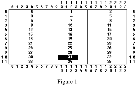 |
If we plot point 10,10 on our sheet of graph paper, we note that it is in division 31 and is the 2nd square of that division (first square of a division is 0). The computer does a similar calculation when we tell it to plot point 10,10. It first determines which byte of the screen memory we want and then it determines which bit in that byte is to be set.
Now this isn't as hard as it looks, because there are several tricks that can be used to make these calculations simple. We can calculate the offset of the first division (byte) of each line by multiplying the number of divisions (3 for our example, 40 for a graphics 24 display) by the line number. We can then calculate which division (byte) we want on that line by dividing the column by 8 (8 spaces per section, 8 bits per byte). Finally, we can compute which square (bit) is to be changed by the remainder of this division. Thus, for 10,10 example we have:
line offset = 30(10*3)
division offset = 1 (10/8)
square offset = 2 (10 MOD 8)
We now have enough information to design our PLOT routine. Remember that we are writing our own routine to increase the speed of plotting points. Multiplication and division are slow operations, so if we avoid doing these operations when we are plotting, it will greatly increase the speed of our plot routine. As turns out, we can avoid doing these operations by precomputing the line offsets and byte offsets at the beginning of the program and then use those offsets in our plot routine. We do this by storing the precomputed offsets in ARRAYs. In the plot routine, we'll use Y as an index into the line Offset ARRAY (line) and X as an index into the byte offset ARRAY (div8).
Walking through.#
The PROCedure Init() is responsible for generating the precomputed line and byte offsets. It starts by setting up the display with:Graphics (24) SetColor(1,0,14) : SetColor(2,0,0)The next block of code computes the line offsets (192 of them for graphics mode 24). The variable scrstart is defined to be location 88. This location contains the starting address of the screen. The variable lineloc is used for computing the address of each line. Initially it is set to the value of scrstart (address of first line), and is incremented by 40 each time through the loop (remember, there are 40 byte per line in graphics mode 24) to compute the address of the next line. The ARRAY line is used to store each value of lineloc. The next loop computes the byte offsets for all possible values of X (0 to 319), and saves them in the ARRAY div8.
PROC Plot() is passed two arguments. X and Y, which define the point to be plotted. The byte that is to be modified on the screen is computed by adding the line address of Y to the byte offset of X as follows:
pos = line(Y) + div8(X)
The BYTE POINTER pos now contains the address of the byte we want to modify. Next, we determine if we are plotting a point or erasing one by:
IF color 0 THEN
If color is non-zero, we want to plot a point. This is done by setting the correct bit of the byte pointed to by pos. This is what
pos^ == % m1(X&7)
does. This may look very complicated, but it isn't. X&7 computes which bit is to be modified (same as X MOD 8, but much faster). This is used as the index for the ARRAY m1. ARRAY m1 is declared to contain a set of 8 masks. Each mask represents the bit to be modified for that index. Thus, when m1(X&7) is or'ed into the byte pointed to by pos, it sets only the bit to be plotted without affecting the other bits of that byte.
In a similar manner, if color is zero
pos^ == & m2(X&7)
erases point X,Y on the screen. ARRAY m2 is declared to contain 8 masks which, when and'ed with the byte pointed to by pos, erase a single bit without effecting the other bits of that byte.
Using this Plot routine instead of the built-in routine increases the execution speed of Kal by about a factor of 3. Since none of the X values used in Kal exceeds 255, you can change the declaration of Plot to be:
PROC Plot (BYTE x, y)
This will make this version of Kal run about 4 times faster than using the built-in Plot routine, but it will no longer work for all legal values of X.
If you haven't followed all of this, don't worry. I didn't go into any details about bit-wise operations (& and %) to keep the description brief. You can still enjoy the results (assuming you have an Action! cartridge). You can even use these two PROCs (Init and Plot) in other programs that you write yourself.
Listing 1.
;         KAL.ACT

; Copyright 1984 BY Clinton Parker
; All rights reserved

; last modified February 18, 1984
TYPE REC=[CARD (nt,ax,bx,cx,ay,by,cy]
REC p, e
CARD period, npts, persistence

CARD ARRAY line(192)
BYTE ARRAY diV8(320)
BYTE ARRAY m1=[128 64 32 16 8 4 2 1]
BYTE ARRAY m2=[$7F $BF $DF $EF $F7
$FB $FD $FE]

PROC Plot(CARD x, BYTE y)
  BYTE POINTER pos

; get address of byte to modify
  pos = line(y) + div8(x)
; modify only one bit of that byte
  IF color#0 THEN ; plot
    pos^ ==% m1(x & 7)
  ELSE ; erase
    pos^ ==& m2(x & 7)
  FI
RETURN

PROC Init()
  CARD i, scrstart=88
  BYTE POINTER lineloc
  Graphics(24)
  SetColor(1,0,14):SetColor(2,0,0)

; get starting address of each line
; on graphics 24 screen

  lineloc = scrstart
  FOR i : 0 TO 191 DO
    line(i) = lineloc
    lineloc ==+ 40
  OD

; pre-calculate small values
; divided by eight
  FOR i = 0 TO 319 DO
    div8(i) = i / 8
  OD
RETURN

PROC Gen(REC POINTER r)
  BYTE x0, y0, x1, y1, ATRACT=77

; get new a
  r.ax = (r-ax + r.bx) ! r.bx
  r.ay = (r.ay + r.by) ! r.by

  r.cnt ==— 1
  IF r.cnt=0 THEN ; get new b
    r.bx = (r.bx + r.cx) ! r.cx
    r.by = (r.by + r.cy) ! r.cy
    r.cnt = period
    ATRACT= 0 ; turn off attract mode
  FI

  x0 = r.ax RSH 9
  y0 = r.ay RSH 9
  IF x0 <= y0 and y0 < 96 THEN
    x1 = 191 – x0
    y1 = 191 — y0
    Plot(x0+64, y0):Plot(x0+64, y1)
    Plot(y0+64, x0):Plot(y0+64, x1)
    Plot(x1+64, y0):Plot(x1+64, y1)
    Plot(y1+64, x0):Plot(y1+64, x1)
  FI
RETURN

PROC Kal()
  CHAR CH=764

  Init()
; change for different patterns:
  persistence = 2500
  period = 10000  p.cnt = period
  p.ax =  5221 p.bx = 64449 p.cx=3
  p.ay = 57669 p.by = 64489 p.cy=3

; copy plot record to erase record
  MoveBlock(e, p, REC)

; handle persistence
  color = 1
  FOR npts = 1 TO persistence DO
    Gen(p)
  UNTIL CH#255 OD

; draw patterns until key depressed
  WHILE CH=255 DO
    color = 1 Gen(p)
    color = 0 Gen(e)
  OD

; ignore key and restore screen
  CH = 255 : Graphics(0)
RETURN
PDF: An Introduction to ACTION/introinaction.PDF

