Ironman Atari - A Compilation of Advanced Atari 8-bit Programming Techniques#
by Mark Schmelzenbach
Table of Contents
- Ironman Atari - A Compilation of Advanced Atari 8-bit Programming Techniques
- Introduction
- Programming Environment
- Hardware
- Assemblers
- Compilers
- Graphics editors
- Sound editors
- Emulators
- Graphics Modes
- Introduction
- Splitting modes vertically
- HIP/RIP
- TIP
- GTIA 9++
- MCS
- Graphics Links and Resources
- Scrolling techniques
- MWP
- Hardware-assisted Parallax Scrolling
- Scrolling by Half-steps
- Using the mouse
- Pushing POKEY
- Digital samples
- Digital Sample Links and Resources
- Trackers
- RMT
- TMC2
- Soft Sprites
- Bitmap sprites
- Character sprites
- Advanced Player/Missile Use
- ORA overlapping for color
- GTIA Gr. 9 overlay
- Reusing players
- Collision detection
- File Access
- xBIOS
- Advanced Graphical Tools
- Rastconverter
- Hardware exotics
- Accessing additional memory
- Double POKEY
- Double GTIA
- Video Board XE
- Ironman Contributors
Introduction#
Welcome to "Ironman Atari", a collection of articles detailing new techniques in Atari 8-bit programming. Although the golden Age for Atari has long passed, several new programming methods have been discovered or rediscovered over the past decade. These new methods push and twist classic Atari iron in ways that might have surprised even Jay Miner himself.
Today, the internet provides a forum that allows people to share information in a manner unsurpassed in the past. This is a compilation of articles gathered for the purpose of preserving this knowledge for future programmers. Who knows? In another 25 years, there may still be people hacking away on their trusty Atari computers. Many of the articles here have been gathered from a variety of sources, including USENET, user forums and solicited articles. Wherever possible credit has been given to the original authors. If you find an attribution that is missing or in error, please contact me so that the attribution can be corrected.
This book will use use two primary reference machines, the Atari 800XL and the Atari 130XE. Both of these reference machines are unmodified NTSC machines. Although there are places where other machines may be required (for instance a PAL machine, the near mythical 320XE, a double POKEY machine, or other hardware exotics) these are exceptions and will be noted as such. In addition, most examples will work fine on a factory standard Atari 800 with GTIA chip unless explicitly stated otherwise. It should also be noted that almost all of these techniques also can be used on the Atari 5200 since this machine has nearly identical graphic hardware as that of the Atari 8-bit computer line.
All examples will be written for ATasm, a MAC/65 compatible assembler, and will assemble on real hardware using MAC/65 unless specifically stated.
It is assumed that the reader is already familiar with the Atari computer platform and assembly language. Additional reference material is provided below:
Atari Graphics and Advanced Arcade Game Design , by Jeffrey Stanton and Dan Pinal. The full text of this book is available on-line at http://www.atariarchives.org/agagd
Atari Hardware Manual Atari Roots, A Guide to Atari Assembly Language, by Mark Andrews. The full text is available at http://www.atariarchives.org/roots
De Re Atari ? By Chris Crawford, Lane Winner, Jim Cox, Amy Chen, Jim Dunion, Kathleen Pitta, Bob Fraser, and Gus Makrea. This is THE seminal work on the Atari home computer and should be considered required reading. The full text can be found on-line at http://www.atariarchives.org/dere
Dr. C. Wacko's Miracle Guide to Designing and Programming Your Own Atari Computer Arcade Games, by Robert Kurcina, David L. Heller, and John F. Johnson. This book can still be found on http://www.amazon.com.
Mapping the Atari! Revised Edition, by Ian Chadwick. The full text can be found online at http://www.atariarchives.org/mapping
Eventually, I would like to see this expand into a larger work with well-commented programs and games that demonstrate the advanced techniques described. It is not just technology that has advanced over the last 25 years, but also the sophistication of the gaming market. There are several games that exist today, particularly on handheld devices such as phones and the GBA/DS/PSP or the emerging Flash based minigame market that are not out of reach for the Atari 8-bit. All it takes is the knowledge to program and the time to do so. Here is to the next 25 years!
--Mark Schmelzenbach, ed.
Disclaimer: As always, errors inevitably creep into a work such as this. If you find an error or better yet, if you wish to submit an article for inclusion in a future release, please contact me.
Programming Environment#
The Atari programming environment has changed dramatically over the last 25 years. Most development work now can be done cross-platform by mere mortals on a PC instead of on specialized mainframes or squinting at a flickering television on the actual Atari hardware. This opens up new realms previously unavailable. Numeric tables and graphics can be precalculated using today's big muscle CPUs to be used by the native Atari. Large projects can be assembled in less than a second instead of listening to the old floppy drive grind away for a quarter of an hour. The assemble/test/debug cycle is greatly reduced by using an emulator instead of waiting for the real iron to reset. This allows for quick itertaion, testing and development of ideas.
The following is a list of my current programming environment. HTML links and short descriptions of each item are provided below. I work under Linux, so most of the items below are heavily UNIX based rather than Windows. Many of the UNIX tools either work on the Macintosh or can be ported with a bit of effort. There are some excellent Windows-only tools, but I do not use these.
Additional disclaimer: I am the author of ATasm and envisionPC.
Hardware #
- Pentium 4 machine running Linux
- SIO2PC cable: These cables can be purchased through the AtariAge store, from Steven Tucker, on eBay, or you can build your own. This cable in conjunction with the proper software turns your PC into a fileserver for the real Atari computer.
- AtariSIO version 0.2.0: AtariSIO is a Linux kernel module and user-level program by Mattias Reichl that allows the use of a SIO2PC cable under Linux. AtariSIO is available at http://www.horus.com/~hias/atari
- AtariMax flash cartridge (1 megabit): This cartridge is available in 8 megabit size. AtariMax flash cartridges are reprogrammable flash-memory based cartridges. This effectively provides extra memory that can be quickly paged in for things like unrolled code loops, look-up tables, etc. More information can be found at http://www.atarimax.com/flashcart/documentation
- Atari800 (NTSC, GTIA, 64K expansion)
- Atari130XE (NTSC, stock)
Assemblers #
- EMACS as primary editor (vi on occasion)
- ATasm v #5: ATasm is highly compatible with the original OSS Mac/65 native compiler. ATasm is written in C, and compiles without modification on any platform that has a GCC compiler. ATasm has been specifically designed for the development of programs for the Atari home computer. It can produces Atari native binary load object files, raw cartridge images, and can optionally target the machine state files produced by many emulators. Binary load files can also be written to disk images for easy loading in other emulators or onto real hardware via SIO2PC. It is available at http://atasm.sourceforge.net
- Another popular assembler that is also Atari specific is XASM by Fox of Taquart. This assembler is compatible with JBW's Quick Assembler, which was the primary assembler used in Poland and other eastern European countries during the 1990s. XASM includes several pseudo-instructions (like mva) and pseudo-indexing modes. In addition, it can generate Atari native binary object files and has includes utilities to create boot disk images. XASM can be found at http://atariarea.krap.pl/x-asm/
- If you are looking for a Linux assembler that is Quik Assembler compatible, try a program called Zooey, found at http://atari8.sourceforge.net/zooey.html
- Another assembler worth considering is the MADS assembler, found at http://mads.atari8.info/; The latest documentation is always provided in Polish, however there is an English translation of version 1.9.5 provided here: http://mads.atari8.info/mads_eng.html
Compilers #
- Some projects have been written using cc65, a version of C that targets the 6502. In addition to providing a high-level language, the project also provides an assembler and a powerful linker, allowing basic library management. cc65 can be found at http://www.cc65.org/. Please note that cc65 is no longer developed, support slowed down and the website will lead you to other sites.
Graphics editors #
- envisionPC is a font/map editing program similar to the original Envision program written for the Atari. It runs on an IBM PC (either Linux or DOS/Windows) and includes all source code. It will load and save maps and character sets to disk images, MAC/65, and Action! formats. It is available at http://atari.miribilist.com/envision/index.html
- gEnvision is another Envision-like program written for Linux written by Larry Richardson. gEnvision will allow you to edit Atari character sets in either single or multicolor modes. It will let you create character based "maps" of up to 256x256 characters. It will save characters sets and maps as MAC/65 source code. gEnvision is available at http://bellsouthpwp.net/r/i/rich5462
- graph2font is a conversion utility for full screen pictures. Graph2Font has evolved into a full-featured graphics editor and conversion tool. The latest version can be found at http://g2f.atari8.info
- GIMP and a number of homebrew tools for graphics conversion
Sound editors #
- RMT: RASTER Music Tracker (RMT) is a cross-platform tool for making music on a Windows PC. RMT uses Atari music routines written by Radek Sterba. The latest version (1.28) is available at http://raster.infos.cz/atari/rmt/rmt.htm. Please note that RMT is no longer supported due to Radek passing away.
- sox: Sound eXchange : universal sound sample translator is a UNIX utility used to convert samples between formats.
- Homebrew tools to convert .WAV to 4-bit samples playable on the Atari.
Emulators #
- Atari800 #3.3 emulator: This is free and portable Atari800/XL/XE/5200 emulator, originally written by David Firth and now developed by the Atari800 Development Team headed up by Petr Stehlik. This is the primary emulator that I use. It has a very nice monitor for debugging and recently has added cycle-exact emulation and greatly improved POKEY emulation. The Atari800 emulator is available at http://atari800.sourceforge.net.
- The Atari++ emulator is also an excellent emulator by Thomas Richter. It was the first cycle-exact emulator and provides many useful functions including a very nice monitor and emulation of Flash cartridges. Atari++ is available at http://www.math.tu-berlin.de/~thor/atari++
- Atari800Win Plus: This emulator is Windows only, but is considered one of the best emulators around. It can be found at http://www.a800win.atari-area.prv.pl.
Although cross-platform development has come a long way, always remember that it is vitally important to test your programs on the real machine. Many of the techniques detailed within require cycle-exact timing and push the hardware in strange ways that emulators may or may not properly emulate.
Graphics Modes #
Introduction #
The first three techniques related in this section rely on ?bugs? in the GTIA chip. The original CTIA chip did not have GTIA modes 9,10,1# However, in early 1982 Atari began shipping with GTIA chip which provided 3 new graphics modes. It appears that the GTIA was originally slated to be shipped with the original units but there were manufacturing issues that delayed production (see Atari History sec?) The new GTIA modes can be selected by setting the display list to ANTIC mode f (graphics 8), and then setting the GPRIOR register appropriately.
- GTIA mode 9 allows 16 shades of a single color
- GTIA mode 10 allows for 8 colors from the Atari palette
- GTIA mode 11 allows 16 colors of a single shade
Splitting modes vertically #
The ?unity? demo by Our-5oft has a screen that displays 3 different graphics modes on a single scan-line: graphics mode 8 (ANTIC mode f), mode.9 and something similar to mode15 (ANTIC mode e). This effect is accomplished by altering the GPRIOR register on-the-fly within a DLI. By writing a 0 into GPRIOR at the beginning of a scan-line, waiting some time, switching to GTIA mode.9 by writing #$40 and finally in the last 1/3 of the scan-line writing a 0 again. Rather than returning the display to mode f, the GTIA becomes confused and displays the remainder of the line as ANTIC mode e. This effect can be seen is several demos, including ?unity? and is used in the game Admirandus by MK-SOFT. Below is a kernel that demonstrates this technique.
dli pha ; preserve registers
txa
pha
tya
pha
ldy #64 ; display is 64 scan-lines tall
wloopsta WSYNC ($d40a)
lda #0
ldx #$41 ; for GTIA 9
sta PRIOR ($d01b)
nop ; wait for ~24 cycles
nop
nop
nop
nop
nop
nop
nop
nop
nop
nop
nop
stx PRIOR ($d01b)
nop
nop
sta PRIOR ($d01b)
dey
bne wloop
pla ; restore registers and exit
tay
pla
tax
pla
rti
This technique can also be used to split between GTIA modes, so with careful counting it should be possible to have 4 or possibly 5 modes on a single line. Determining a good reason to do this is up to the game author.
Notice that this technique will work in text modes as well as in graphics modes, but cycle counting becomes problematic in text modes as ANTIC steals extra cycles every x number of scan lines to refresh the character map.
HIP/RIP #
This section is based on a translation of the original article published in Polish magazine "Atarynka", no. 2/2002 and the original HIP FAQ written by Heaven of Taquart. HIP (HARD-Interlace Picture) was discovered by members of HARD Software in 1996. This mode allows a nearly flicker-free display of 30 shades with a resolution of 160x200. The basic idea exploits a bug discovered with the GTIA that appears when alternating between lines of GTIA 9 and GTIA 10. Whenever a GTIA 10 line is displayed, the GTIA chip ends up shifting the line by half of a pixel. Interlacing two alternating display lists allows the generation of an apparent 160 pixel horizontal resolution. It should be noted HIP is not the first to experiment with mixing GTIA modes. However, earlier techniques such as APAC mixed modes 9 and 11, yielding a display of capable of 256 colors. Mixing these modes does not cause the GTIA to shift, and so displays that did this were limited to a horizontal resolution of 80 pixels. A HIP display consists of two alternating display lists and associated pictures. This is shown below in figure ??. By appropriately selecting the GTIA mode 10 palette and carefully placing the mode 9 pixels, HIP has an average bit-depth of HIP of 3.5 bits. (GTIA mode 9 has 4 bits, GTIA mode 10 has 3).
| DLIST ONE | DLIST TWO |
|---|---|
| mode 9 | mode 10 |
| mode 10 | mode 9 |
| mode 9 | mode 10 |
| mode 10 | mode 9 |
| ... | ... |
Since GTIA mode 9 obtains its background color from register 712 and mode 10 obtains its background color from register 704, it is easiest to assign the palette as follows:
704 $00 708 $08 712 $00
705 $02 709 $0A
706 $04 710 $0C
707 $06 711 $0E
This method ends up ?wasting? a color register since registers 704 and 712 are both set to the background color. However, it simplifies the DLI routine as now only the GPRIOR register needs to be set instead of alternating the background registers on every line. By selecting the above colors, a palette of 30 colors becomes available in HIP by selecting the appropriate color in each display list as detailed below:
| 9 | #000 | #111 | #222 | #111 | #222 | #333 | #444 | #333 | #444 | |
| 10 | #000 | #000 | #000 | #222 | #222 | #222 | #222 | #444 | #444 | |
| HIP | #0.0 | #0.5 | ##0 | ##5 | #2.0 | #2.5 | #3.0 | #3.5 | #4.0 | |
| 9 | #555 | #666 | #555 | #666 | #777 | #888 | #777 | #888 | #999 | |
| 10 | #444 | #444 | #666 | #666 | #666 | #666 | #888 | #888 | #888 | |
| HIP | #4.5 | #5.0 | #5.5 | #6.0 | #6.5 | #7.0 | #7.5 | #8.0 | #8.5 | |
| 9 | #AAA | #999 | #AAA | #BBB | #CCC | #BBB | #CCC | #DDD | #EEE | |
| 10 | #888 | #AAA | #AAA | #AAA | #AAA | #CCC | #CCC | #CCC | #CCC | |
| HIP | #9.0 | #9.5 | #A.0 | #A.5 | #B.0 | #B.5 | #C.0 | #C.5 | #D.0 | |
| 9 | #DDD | #EEE | #FFF | |||||||
| 10 | #EEE | #EEE | #EEE | |||||||
| HIP | #D.5 | #E.0 | #E.5 |
To display a HIP picture, a special display list set can be constructed that alternates between screens every frame. In addition, two DLI routines need to be written: one to alternate between GTIA modes 9 and 10 and the other to alternate between modes 10 and 9. A simple display routine is included below.
HIP pictures are difficult to create because the pixels cannot be independently set. This is due to the fact that we are simulating a 160 pixel wide display by overlapping two offset 80 pixel displays, as seen in the figure below. So, in order to reduce flicker, no two HIP pixels should vary their luminance by more than 2 shades. This tends to favor pictures that are digitized or ray-traced. This limitation makes drawing HIP pictures by hand extremely difficult. As a result, the best way of generating HIP pictures is to convert it using a program on a cross-platform machine. There are several converters available of varying degrees of sophistication Refer to the links section at the end of this chapter to find an appropriate converter.
mode 10 .. 00 00 22 22 44 44 ..
mode 9 .. 00 00 22 22 ..
HIP .. 00 11 22 33 ..
There is another drawback that is a result of interlacing pictures, a single HIP pixel vertical line is impossible. This is seen as a wavy borders on the vertical edges of most HIP pictures. Fortunately, this can be fixed with judicious use of Player/Missiles. Remember that register 704 is set to the background color. Register 704 is also used as the color for player 0 and its missile. By setting the shape of player 0 and missile 0 to a solid strip, they can be used as borders. This provides the picture solid frame. There is a simple extension to the HIP format to provide color instead of only allowing a monochrome pallet. This is known as the RIP (Rocky Interlace Picture) file format. RIP allows modification of the color registers on each GTIA 10 lines. This allows for non- monochrome pictures, but RIP pictures selection is not straight-forward.
TIP#
This section is based on a translation of the original article published in Polish magazine "Atarynka", no. 2/2002.TIP (Taquart interlace picture) is another method of adding color to HIP. This method combines the original HIP format with ideas demonstrated by the original 256 color modes mentioned above. Colors are added by introducing a GTIA 11 line above each HIP GTIA 9/10 line as shown in the figure below. Unfortunately, adding this extra line halves the vertical resolution and introduces dark lines. On the other hand, pixels are now square, which helps conversion.
| DLIST ONE | DLIST TWO | |
|---|---|---|
| mode 11 | mode 11 | |
| mode 9 | mode 10 | |
| mode 11 | mode 11 | |
| mode 10 | mode 9 | |
| ... | ... |
TIP pictures can be converted manually from a 24-bit picture in following manner. First, scale or crop the picture to an appropriate size (160x120). Second, map the picture to the Atari color palette. Note that the 256-color Atari palette is available in PhotoShop format in the Atari800 emulator package. (This can also be read by GIMP). Finally, the color information and ?HIP-data? need to be separated. The easiest way of obtaining the color data is to take the color of every second pixel. Conversion of shades to HIP can be problematic, but a reasonable method is to take the shade of every second pixel (starting from the first) for mode 9, and the other pixels' for mode 10. Use all four bits for GTIA 9 shades and ignore the lowest bit for mode 10.
Taquart has released the source to their incredible ?Numen? demo (which demonstrates many of the techniques described here). As part of the source release, they have a few conversion utilities including a HIP to TIP colorizer utility and a simple PCX to TIP converter.
GTIA 9++#
This text is based on a translation of the original article published in Polish magazine "Atarynka", no. 2/2002 by Piotr Fusik (Fox/Taquart); The textmode discussion is from Jaskier on AtariAge programming forumBefore GTIA 9++ was developed, the graphics mode most often used by demo writers was a mode called ?Konop's mode.? This mode was first seen in the Asskicker demo written by Konop/Shadow. Konop's mode has square pixels, 16 shades, and a small enough memory-bartprint that the entire screen can be updated in a single vertical blank (depending, of course, on the complexity of the drawing routines). When Konop's mode is used in GTIA mode 9, it is also referred to as GTIA 9+. Konop's mode is generated by creating a specialized display list. Each mode line is generated by a the following:
$0f line of mode 15
$00 blank line
$4f <screen>line of mode 15 + LSM
$00 blank line
Fox/Taquart discovered a way of generating a new graphics mode that has many of the same strengths as Konop's mode, but without requiring the use of blank lines. This mode has been dubbed GTIA 9++ (or GTIA 10++, depending on the base GTIA mode in use).
In addition to the cleaner looking display, GTIA++ has a few other advantages over Konop's mode:
- The display list is significantly shorter.
- The display list only uses one LMS instruction, so instead of using two display lists for double-buffering, the screen-address in the DL can be directly altered.
- The height of each line mode can be easily modified (up to a height of 16 pixels).
- ANTIC takes less cycles to display a GTIA 9++ mode. This comes as a trade off for some extra work for the CPU. Although not much is required of the CPU, the work must be carefully synchronized with the display. This means that a simple implementation of GTIA 9++ will not show significant savings. A less naïve method can be written with additional programming effort.
- The method used can be used in other ANTIC modes to generate, for example, a hardware-supported 40x40 text-mode. TMC 2.0 uses this technique to create a textmode screen of 40x39. See the discussion at the end of this section for more details.
The basic idea underlying GTIA 9++ is simple: force ANTIC to repeat the same line multiple times using its internal memory. ANTIC normally does this when generating native modes. Consider ANTIC mode 8 (Graphics mode 3), which is a 40x24 display. In this mode, ANTIC generates the first displayed scan-line by retrieving it from main memory but proceeds to generate the next 7 scan-lines from its own internal memory. ANTIC tracks the vertical dimension of each scan-line with a four-bit counter called the Delta Counter (DCTR). Normally the DCTR starts at 0 and repeats each scan-line until it reaches a count specific to each mode. In ANTIC mode 8, this count is 8 in ANTIC mode e this count is 0.
Unfortunately, the DCTR is not directly accessible by the CPU. However, the behavior can be indirectly effected. It turns out that the DCTR acts differently if vertical scrolling is enabled. On the very first vertical scrolled line, the DCTR will count from the value in VSCROL to 0. On the very last vertical scrolled line, the DCTR counts from 0 to VSCROL. Everywhere else, the DCTR behaves normally. At the beginning of each mode line, DCTR is loaded with the appropriate value (either VSCROL or 0). Near the end of each scan-line, the DCTR is compared with the terminating value (either the mode specific count, or VSCROL). If the DCTR and the terminating value are equal, the next display list instruction is fetched otherwise the DCTR is incremented and the line is repeated.
Consider the following display list, using ANTIC mode 8 and VSCROL set to 6:
$28 line of mode 8, vertical scroll bit set
$08 line of mode 8, vertical scroll bit clear
$08 line of mode 8, vertical scroll bit set (last line of the display)
$41 <dlist>jump to top of the display list
The native behavior is for the first line of data to be visible for 2 scan-lines (DCTR values 6, 7); A match is made and the next line of data is fetched from main memory. This line is seen 8 times (DCTR values 0,1,2,3,4,5,6,7) before its count is reached. The final line is seen for 6 scan-lines (DCTR values 0,1,2,3,4,5). So, in order to produce a mode 9++ screen, the values of VSCROL must be set appropriately to cause ANTIC to repeat itself. Consider following very short display list:
$2f line of mode 15, vertical scroll bit set
$0f line of mode 15, vertical scroll bit clear
$41 <dlist>jump to top of display list where VSCROL is set to 13.
In this case, the first line will be seen 4 times (DCTR values 13,14,15,0 - DCTR wraps from 15 to 0, because it's 4-bit), while the second line will be seen 14 times (DCTR values from 0 to 13). Similarly, if VSCROL is set to 3, the first line will be seen 14 times and the second will be seen 4 times.
So, in order to have each line repeated 4 times, the following display list should be created:
$6f <screen>line of mode 15, LMS, vertical scroll bit set
$0f line of mode 15, vertical scroll bit clear
$2f line of mode 15, vertical scroll bit set
$0f line of mode 15, vertical scroll bit clear
...
and the VSCROL register needs to be updated at the proper time.
DCTR
 13 @-------------------------
 14 --------------------------
 15 --------------------------
  0 --------------------------
  0 ==========================
  \1 ==========================
  2 ==========================
  3 ====!==================*\#\#
        \\--visible screen--/

'-' - first mode line (bit 5 in DL is set)
'=' - second mode line (bit 5 in DL is clear)
'@' - VSCROL must contain 13 here
'!' - Start of DLI
'*' - VSCROL must contain 3 at this point
'#' - here we put 13 into VSCROL
This diagram shows two lines of GTIA 9++ (8 scan-lines). Initially, VSCROL must be set to 13. (Technically, because DCTR is a 4-bit register, the high nibble may be anything). As soon as ANTIC loads DCTR with this value, the first line will be displayed correctly. The second line will proceed to load properly. It is only near the end of the last scan-line of the second line that VSCROL must be set to 3. This allows plenty of time, and may be set on the DLI of the first line. The difficulty comes in preparing ANTIC to display the third line. As demonstrated in the diagram, there is only a very narrow window, consisting of only a few cycles, in which to write 13 into VSCROL. Manipulation of the VSCROL register can be done in three ways:
- using a DLI
- inside of unrolled effect code
- using a POKEY timer IRQ
The first implementation is clearly the easiest, but it is also the slowest. The second implementation is optimal, but correctly timing code loops realistically constrains this to simple effects. The third option performs better than the first since POKEY timers can be set with single cycle accuracy, removing the time wasted in a WSYNC. However, using a POKEY would cost a the program a valuable sound channel. As such, the first implementation will be the method described here.
In order to reduce the amount of time wasted in the WSYNC, the number of DLIs should be as small as possible. Using a DLI every second mode line, (once every 8 scan-lines), is sufficient. The DLI should be set for every line where the vertical scroll bit is clear. The easiest way to ensure proper synchronization is to use WSYNC. Then write 13 to VSCROL and followed by the 3. The following code provides a simple kernel to do this:
         dli pha
         sta WSYNC  ;($d40a)
         lda #13
         sta VSCROL ;($d405)
         lda #3
         sta VSCROL ;($d405)
         pla
         rti
So, how many cycles does GTIA 9++ save over Konop's mode? Each mode line in Konop's mode costs 6 cycles for the display list plus an additional 64 or 80 cycles for the screen, depending on width. GTIA 9++ takes only one cycle per line plus 32 or 40 cycles for screen data. In addition, VSCROL must be updated which takes a further 6 cycles. For an entire screen 59 lines high the following costs are incurred:
Narrow screen: Konop: 1+59\*(6+64)+2+3=4136 9++: 1+59\*(1+32+6)+2+3=2307
Normal screen: Konop: 1+59\*(6+80)+2+3=5080 9++: 1+59\*(1+40+6)+2+3=2779
This indicates that there is about a 6-7% gain in CPU time using GTIA 9++.
Unfortunately this is only true if GTIA 9++ is implemented using the optimal code unrolling method (implementation 2 in the earlier list). If a DLI is used to update VSCROL then Konop's mode is faster. One possible compromise is to use the time before the WSYNC for calculations. In addition, traditional uses of DLIs (color changes or P/M multiplexing) can be had at nearly no additional cost.
As a final caveat, while Konop's mode can be trivially extended to 240 scan lines by placing the JVB at the end of the display list, GTIA 9++ has problems displaying graphics in this last line. Either remain satisfied with 59 lines or reduce the top or bottom line to a height of 3 scan lines.
The native music tracker TMC 2.0 uses the same VSCROL technique described above to create a 40x39 character display. To do this, first a custom character set must be designed using an 8x6 font. Then, set up a display list with alternating text lines with the vertical scroll bit set. Note that as the text lines alternate down the screen, sometimes the first 2 lines of the font are cut and sometimes the bottom two lines are cut. This requres the use of two character sets. The DLI from TMC 2.0 looks like the following:
         dli pla
         sta WSYNC ;($d40a)
         lda linewsk
         sta VCROL ;($d405)
         eor #7 ; toggle between 2/5
         sta linewsk
         lda fontwsk
         sta CHBASE ;($d409)
         eor #4 ; toggle between two fonts
         sta fontwsk
         pla
         rti
This mode could be emulated in software by using a Graphics 8 screen. However, the hardware supported mode takes less memory. A Graphics 8 screen takes 7680 bytes for display, ~200 bytes for the display list, and 1024 bytes for the custom display font (although the font could be restricted to only characters used in the display). This text mode takes 1560 bytes for the display, ~42 bytes for the display list, and 2048 bytes for the font. (DMA cycles here too)
MCS#
Something about MCS and/or graph2font conversionsGraphics Links and Resources #
- Original HIP FAQ
- Original Mode9++ document
- ?Numen? link
- ?Asskicker? link
- ?unity? and other
- MCS demo
- HIP converters
Scrolling techniques #
MWP #
The usual method of scrolling on the Atari is to create the entire logical display in memory, and then use ANTIC to pan across this display. This method is easy and very efficient, requiring very little CPU time. The only problem occurs when it is infeasible to hold the entire logical display in memory at one time. If this is the case, then it becomes necessary to either generate the display on demand or reduce the scope of the game.
The traditional method of generating the display on-the-fly is the method that most other platforms are forced to use. The most straight forward method of doing this involved creating a double-buffer. Show one screen to the player, while creating the next frame in memory appropriately shifted. When this second screen is complete, wait for the VBLANK, then flip it onto the display and start work on the first screen. This method can be extended by using a technique called triple-buffering which never waits for the VBLANK, but instead immediately starts work on the third screen. In this manner, no CPU cycles are wasted waiting for the vertical blank, and the CPU is always working.
Triple-buffering was used effectively in the IBM-PC game ?Jazz Jackrabbit? by Epic MegaGames in the early 1990s. It is also the method that should be used if a game being presented in first-person perspective. For instance, the Atari port of Space Harrier by Chris Hutt uses triple-buffering to help keep the frame-rate up.
Analogue Multiplexer created a way to generate the screen on demand, but without requiring large memory copying. This allows the program to forgo the double or triple buffer and dramatically reduces CPU usage. This new scrolling technique has been named the minimum-wrapping-principle (MWP).
MWP scrolling combines the strengths of traditional Atari scrolling and scrolling created by on-demand screen generation. The primary advantages are:
- The memory required for the displayed map is just over the requirement for one screen. Remember, however, that the logical source data still needs to be in memory. See the discussion of when to use MWP below for further information.
- Large amounts of data copying is not necessary, only one row or column buffer needs to be written at one time.
- Only 2 LMS commands in the display list
Although MWP scrolling described here is for a character mode screen, the same principle can be applied to a bitmap screen. In fact, it was during a discussion of scrolling bitmap screens that MWP was developed.
The basic idea of MWP is to wrap the screen around onto itself, a bit like taping the ends of a piece of paper. To demonstrate this, consider a 3x3 display. MWP requires that one row be duplicated, one copy at the beginning of screen memory and the one at the end of screen memory. This means that in order for a 3x3 display to be appropriately created there must be 4 rows in all. For this example, suppose that screen memory begins at address $6000. It then follows:
Row 0: $6000-$6002
Row 1: $6003-$6005
Row 2: $6006-$6008
Row 3: $6009-$600B
This display is shown in the following diagram.
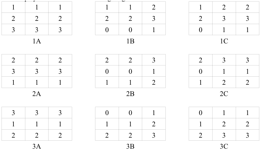 |
Notice that rows 0 and 3 are exact duplicates of each other. This is necessary in order to properly perform wrapping from row 3 back to row # This can be seen in figure 1B. Initially, the screen will start in the state shown in figure 1A. If vertical scrolling is performed, the display list moves from 1A > 2A > 3A > 1A and so on. The lowest row is hidden off-screen and is used as a buffer. If row 0 or 3 is written into, then a copy must be made to rows 3 or 0 respectively.
When scrolling horizontally, the entire sequence is cycled:
1A > 1B >1C >2A >2B >2C >3A >3B >3C >1A and so on. In this case, the rightmost row is off of the screen and should be written into as a buffer. Again, if data in row 0 or 3 is modified, that modification needs to be reflected in the other row.
Note that although the starting state may differ, the flow will remain the same. So, scrolling
Wrapping from row 3 to row 0 is performed via an LMS instruction. This means that MWP has two LMS instructions, one at the top of the screen, and a second LMS wherever row 0 has to be displayed. Using the LMS to wrap the screen is what eliminates the need for a full screen copy.
Hardware-assisted Parallax Scrolling #
Scrolling while backtracking with characters either dynamically or via flipping through 4 separate character sets (in ANTIC 4).
Note C64's ?Flimbo's Quest?
Scrolling by Half-steps#
It is possible to scroll high resolution graphics (320 pixels wide) at half a color clock at a time. This can be accomplished by using soft sprites in Antic F and redrawing the items each frame. Alternatively, hardware assistance can be provided by using two Antic 2 character sets shifted by a single pixel. The scrolling routine would then look like: character set flip, fine scroll step, character set flip, fine scroll step, then eventually a coarse scroll.One thing to be careful about when using this technique is color artifacting. Be sure to check on real hardware to ensure your objects' are not color strobing.
Similarly, it is possible to scroll carefully designed GTIA graphics a single color clock at a time. Basically, it is possible to exploit the pixel shifting property observed in the HIP/TIP discussion above. Graphics 9 and Graphics 10 pixels are 1 color-clock shifted. By designing an 8 shade item, and carefully mapping the Graphics 10 palette to match the shades of the Graphics 9 palette, you can flip screens (or character sets, if you are using GPRIOR modes in Antic 2 instead of Antic F) between fine scrolling. The scrolling routine then looks like: flip image (or character set) and GPRIOR to mode 9, flip image (or character set) and GPRIOR to mode 10, fine scroll, flip image and return to GPRIOR mode 9, etc.
Note: Another, much more limited method is possible by using player-missiles as masks to fake the fine scroll. By placing players set with the background color at the leading and tailing edge of a GTIA shape, the player can mask the item underneath. The scrolling routine would then consist of moving the players, then shifting the shape. The biggest problem with this method is that in order for the illusion to work, each scanline of the object can only have 1 color. This is due to the fact that only the object silhouette is ?moving? at the single color clock rate -- the interior detail will remain static and the illusion will be lost.
Using the mouse#
This section is based on a news posting by Jaskier/Taquart (Marcin Lewandowski) Reading a mouse can be difficult because of the sample speed required. Most drivers end up reading the mouse movement via IRQ (like timer 1) or via a specialized DLI routine. If the mouse is not sampled quickly enough, it will tend to drift or track backwards. Unfortunately, this can eat up a lot of processor time, leaving very little time for other purposes. However, Marcin Lewandowski posted a new method of reading the mouse that is not as CPU intensive. His article is included below.
The main procedure below must be continuously called. Fortunately, the VBlank interrupt is fast enough to do this. After a long break, the init procedure must be called to force synchronization.
Main proc:
          lda $d300
          lsr a
          lsr a
          lsr a
          lsr a
          pha
          and #10 ; (#3 in ST)
          ldy #3  ; check left-right move
l1       cmp htab,y
          beq l2
          dey
          bne l1
l2       tya
          clc
          adc #1
          and #3
          cmp xind
          bne l3
          sty xind
          dec xcur
l3       tya
          sec
          sbc #1
          and #3
          cmp xind
          bne l4
          sty xind
          inc xcur
l4       pla
          and #5 ;(#12 in ST)
The main routine above only handles the horizontal axis. The vertical axis is identical, except for the following replacements: change xind to yind,;xcur to ycur; and htab to vtab.
The initialization routine is listed below:
init
          lda $d300
          lsr a
          lsr a
          lsr a
          lsr a
          pha
          and #10 ; (#3 in ST)
          ldy #3
i1       cmp htab,y
          beq i2
          dey
          bne i1
i2       sty xind
          pla
          and #5 ; (#12 in ST)
          ldy #3
i3       cmp vtab,y
          beq i4
          dey
          bne i3
i4       sty yind
The tables referenced by the above code vary depending on the mouse being used.
| Amiga: | Atari ST: | ||
|---|---|---|---|
| htab: | 0,2,10,8 | 0,2,3,1 | |
| vtab: | 0,1,5,4 | 0,8,12,4 |
Oddly, no emulator currently supports the use of a mouse, so this will only work on real hardware.
Note that the Atari can only read the left mouse button of an unmodified mouse.
However, a simple hardware modification on the ST mouse allows its younger cousin to read the second mouse button by watching POT1 to be pulled low. To prepare the ST mouse for use, turn the mouse over and remove the screws. Find where the cable is connected to the printed circuit board, then take a 4.7 kilohm or 5.6 kilohm. resistor and stick one leg into the hole where the red wires is and the other one where the white one is. When you press the right mouse button, the value of POT1 should change from 228 to a value below 9.
Pushing POKEY #
Digital samples #
POKEY is capable of playing digital sound by setting the channel to volume only and then rapidly storing values into the volume register. Volume on the Atari is only a 4-bit register, so digital samples are limited to 4-bit resolution. Although it limits the sound quality possible, it does halve the memory requirement per sample. The first digital sampling and playback routines I used came with an interesting device called the Parrot.
This device plugged into the joystick port on the Atari and was read as a paddle. By rapidly sampling POT0 and storing this into memory, the Atari was capable of recording and playing back digital samples. Now, however, it is easier to record a sound on the PC (or rip from another source) and convert it into the appropriate format for the Atari.
Sample conversion is easiest to do in steps. The first is to convert the original sound into an unsigned 8-bit sound at an appropriate sample rate. For the playback routine described below, this should be about 3.9khz.
Initial sample conversion can be performed with a tool such as sox.
sox infile.wav -t raw -r 3900 -u -b -c 1 outputfile.raw
Depending on the sound source, it may be a good idea to add a low-pass filter when downsampling. See the soxexam man page for more details.
Once a sound is in unsigned raw 8-bit format at the appropriate sample rate, a second conversion pass needs to be mad to convert the raw sound to 4-bit big-endian sample. A program to do this is included in the iron archives called rawtoatari. rawtoatari simply reads in each pair of bytes from the input file, strips off the lower nibble, and combines the bytes into a single byte in big-endian format. Here is a quick C snippet to do this:
#include <stdio.h>
int main(int argc, char argv) {
  FILE *in, *out;
  unsigned char a,b;
  int c=0;
  if (argc!=2)
    return -1;
  in=fopen(argv,"rb");
  if (!in)
    return -1;
  out=fopen(argv,"wb");
  if (!out)
    return -1;
  printf("Converting '%s'...n",argv);
  while(!in.feof()) {    / Conversion routine */
    a=(fgetc(in)&0xf0)|((!feof(in)?fgetc(in):0))>>4;
    fputc(a,out);
    c++;
  }
  fclose(in);
  fclose(out);
  printf("Wrote %d bytes to file '%s'.n",c,argv);
  return 0;
}
Once an Atari native sample has been created, a playback routine is required before it is useful. The more CPU time can be devoted to the task of playback, the clearer the sample will be, and the higher sample rate can be used. Optimally, the playback routine should shut-off the DMA, and all non-vital interrupts and devote complete time to playback. However, realistically, a game or demo will want to display something on screen. So, a compromise must be made. One method used by Chris Hutt in his Space Harrier conversion is to use the VCOUNT register to synchronize playback, creating a solid playback frequency. (Note: this routine has since been replaced with in Space Harrier XE. Now, the sample playback is preformed via IRQs) Another possibility is to include the playback inside of a DLI routine.
; play_sample, a routine to slave processor to play digital sample
; taken from the Space Harrier conversion project
; (c) Chris Hutt, 2000-2004
play_sample
         .local
         lda #0
         tay ; 1st byte of sample data
         sta sample_nibble ; initialize counters
         sta sample_index
?0a
         lda #80
         cmp VCOUNT
         bne ?0a
         sta next_vcount
?0                                     ; setup vcount value to wait for
         lda next_vcount
         clc
         adc #2
         cmp max_vcount          ; max value of vcount is 130 or 155 on PAL
         bcc ?1
         sbc max_vcount          ; wrap to 0 if 131/155 or 1 if 132/156
?1
         sta next_vcount
         lda sample_nibble
         eor #1                            ; toggle nibble count between 0 and 1
         sta sample_nibble
         beq ?2

         ; handle high nibble of data
         lda (sample),y
         lsr a
         lsr a
         lsr a
         lsr a ; shift high nibble into lo byte
         ora #16 ; turn on volume only bit
         tax
         bne ?4 ; always branch

         ; handle lo nibble of data
?2
         lda (sample),y
         and #15
         ora #16
         tax
         iny ; increment byte pointer for next byte
         bne ?3
         inc sample+1
?3
         lda sample+1
         cmp dest_A+1
         bne ?4
         cpy dest_A
         beq ?6
?4
         lda next_vcount          ; wait for specified vcount. 3.9khz is every 2
?5
         cmp VCOUNT
         bne ?5
         stx AUDC3                   ; play sample
         jmp ?0                         ; always loop
?6
         lda #0
         sta AUDC3                   ; switch off volume only
         rts
Digital Sample Links and Resources #
(Note: Update to Sheddy's new IRQ player)Trackers #
RMT #
A RMT module file is standard Atari binary file with from-to head data, because it contains many tables of pointers (with absolute memory values, not relative values). If you save the music with function "Save as.../RMT file", the module will use a hard-coded default address ? starting at address $4000.
If you want use RMT music in your program, you should use "Export as.../RMT stripped file". Then you can specify an arbitrary location for your RMT module data. In addition, this will only save the features used by the module, without any redundant bytes, instrument names, unused songs, and so on.
(Using RMT engine for sound effects in-game as well as for music)
TMC2 #
The Theta Music Composer is a tracker that runs on native hardware.
http://jaskier.atari8.info/menu2/TMC2/TMC2.zip
Soft Sprites #
Bitmap sprites #
Consider massively unrolled loops, hard-coded sprite data, and preinitialized zero page vectors (from NRV's softsprite thread on AtariAge)
Character sprites #
(Turrican, BeyondEvil, etc)
Advanced Player/Missile Use#
ORA overlapping for color #
Player/missile graphics and playfield graphics can be made to mix. Set the lower nibble of GPRIOR to 0, and playfield 0,1 and players 0,1 combine their colors by ?or'ing? the colors together. Playfield 2,3 and players 2,3 are also ?or'd.?. Used in combination with soft-sprites above, this can be used to create modern looking avatars.
Note that setting bit 5 causes the same behavior between players. ANTIC will performs a logical OR of colors of players 0/1 and 2/3 when they overlap. If the overlap option is not set, the area of overlap for all players will be black. (Really? Mapping the Atari claims this, but I do not remember this being the case)
GTIA Gr. 9 overlay #
GPRIOR set to $50 in GTIA 9enables missile "OR" mode, in which overlapping missiles on GTIA mode 9 cause transparency effects.Reusing players #
Changing position, color AND shape of a single PM on a single line.Collision detection #
Hardware registers no longer mean anything, use masks, bboxes, etc.
File Access#
xBIOS#
xBIOS is almost like a programmers version of DOS. With it you can easily access files from your programs without using Atari DOS. It is smaller than DOS and therefore saves memory in your programs. You can even run programs from as low as $0200. xBIOS can read and write from/to existing files but can not write new files or directories from your programs.
Link to official xBIOS page (Polish)
Advanced Graphical Tools#
Rastconverter#
Rastaconverter is a Windows/Linux based utility which iteratively converts ordinary jpeg/gif/png files into executable files which display the pictures natively on the Atari 8-bit. Rastaconverter uses all the power of display list interrupts and player missile graphics to allow the maximum number of colours possible on the screen concurrently. https://github.com/ilmenit/RastaConverter
Hardware exotics #
Accessing additional memory#
Document laying around somewhere on this (see 8-bit news FAQ?).
Double POKEY #
No idea at all.
Double GTIA #
In development - no idea at all.
Video Board XE #
Electron (aka Tomasz Piórek) has been working on a project that adds a new video card
to the Atari computer. This works along side the GTIA chip, but adds several new
features, including a sprite blitter capable of displaying sprites in 256 colors ranging in
size from 1x1 to 256x256. For more current information, video clips of current output
and more, visit the current homepage at http://vbxe.atari8.info/.
Ironman Contributors #
- Analogue Multiplexer (Analmux): MWP
- Fox/Tarquat (Piotr Fusik): GTIA 9++
- Heaven/Tarquart: HIP, TIP
- Sheddy (Chris Hutt): Digital sample playback
- Jaskier/Taquart (Marcin Lewandowski): Mouse driver
- Mathy van Nisselroy: Hardware mouse modifications
- Snicklin (Steve Nicklin): xBIOS
- Mark Schmelzenbach: Editor