
OS/A+ Version 4 ; OSS DOS II+ Version 4.2 ; Copyright (C) 1984 OSS, Inc.#
( information from the OS/A+ Version 4 Handbook )
ATR image#
Version 4 File Structure#
OS/A+ version 4 is an operating system which provides all the power and flexibility of the Atari CIO scheme and also uses an advanced File Management System (FMS) to provide fast and effective random access files. OS/A+ version 4, as it appears to the user, is virtually identical with OS/A+ version 2, except that it work with disk drives ranging in storage size from 128K bytes to over 15 Megabytes.
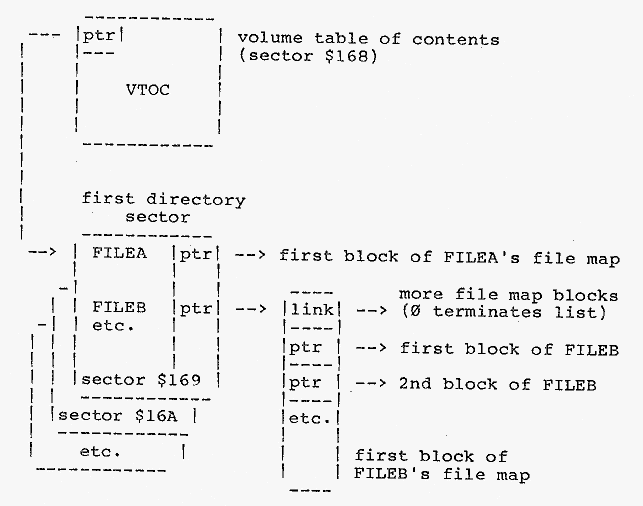
OS/A+ version 4 utilizes a mapped file structure which allows true random access to data files. In such a scheme, special segments of a file act as pointers to the blocks of data comprising a file. By allowing the user to specify the size of the data blocks pointed to, OS/A+ is able to handle large and small files and disks with unsurpasssed speed and utility.
The OS/A+ random access file managment system treats each disk under its control as a collection of contiguous physical- sectors of either 256 or 512 bytes in length, which are numbered starting with sector zero. These sectors are logically grouped into blocks of n sectors in length, where n is a power of two between I and 128. All files on a disk are allocated space in segments of at least one block in length.
 |
There are several non-obvious advantages to this scheme, so bear with us as we try to explain some of them.
- We are able to handle disks with 128, 256, or-512 bytes per sector. (To be truthful, with 128 bytes per sector drives we would use pairs of sectors to emulate 256 byte sectors, since a 128 byte file map is not really adequate.)
- We allow each DISK DRIVE to be assigned its own "drive blocking factor". That means that a quadruple density floppy might have blocks consisting of two 256-byte sectors while a 10 MB disk might use blocks of four 512-byte sectors. Note that this concept of blocking factors is not new or unique: CP/M 2.2 allows blocking factors of IKB, 2KB, and 4KB, depending on disk size. We are simply a little more flexible.
- We allow each FILE to be assigned its own "file blocking factor". Thus, even on a floppy with 512 byte blocks, a given FILE may use 8 KByte blocks, thus guaranteeing at most one disk read to access any given sector of the file. (On the Apple II version of this product, where the drive blocking factor is perforce 1 for standard Apple drives, a file blocking factor of 8 -- 2 KByte blocks -essentially doubles random access speed.)
- Although not yet implemented nor planned for first release, the directory structure is set up in such a way that, if desired, we could implement multiple and/or hierarchical directories (ala UNIX, for example). Even CIO (on the Apple II) has been altered to support the concept of a default device and/or directory.
- Random access files are easy and practical. Unix-like "LSEEKs" are accomplished (via the "POINT" XIO call in section x.xx) to any byte of any file.
- Except for those rare programs that somehow depend on having 125 bytes of data per sector, current Atari application programs (including Atari BASIC and programs written thereunder) will notice NO CHANGE in their interface with the operating system. Of course, some of the currently unused options will be available to take advantage of such features as file blocking factors, but they will not be necessary to the proper functioning of the system.
THE VERSION 4 VTOC#
In order to keep track of what blocks on a particular disk are available for use, the file manager maintains a special section on each disk known as the volume table of contents, or VTOC. The VTOC on a disk consists of 1 or more sectors which contain the bitmap (a long string of bits in which the Nth bit represents the Nth block on the disk). Each bit may be turned on or off to free or allocate (respectively) the block it represents. Note that the VTOC is the only data area on the disk allocated by sectors instead of blocks. The format of the VTOC is as follows:
| hex offset | value | |
|---|---|---|
| 0 | unused | |
| 1-2 | block no. of first directory sector | |
| 3 | unused | |
| 4-5 | unused | |
| 6 | unused | |
| 7-26 | unused | |
| 27 | max. number of pointers in file map sectors ($7A for disks with 256-byte sectors; $F4 for 512-byte sector disks) | |
| 28-2F | unused | |
| 30-33 | unused | |
| 34 | unused | |
| 35 | unused | |
| 36-37 | unused | |
| 38- | disk block bit map |
THE DIRECTORY#
The disk directory holds information describing the existing files on a particular disk. The directory is allocated on the disk by disk blocks, each sector of which holds information on a certain number of files (7 for 256-byte sectors, 14 for 512-byte sectors). The blocks themselves are linked, each one holding the disk address (block number) of its successor, with the last block having a null link (block number = 0). Each entry of the directory describes a particular file. An entry for a single file contains the file's name, its length in sectors (see exceptions for DOS 3.3 diskettes), its file type byte (see below), and a pointer to the start of the file map for that file.
The file name consists of a string of up to 30 characters excluding spaces, commas, carriage returns, or nulls. Characters within a directory entry will have their upper bit inverted. the file name will be padded at the right with inverse video blanks (hex $AO).
The file type byte is used as follows:
BITS 0-3: file use type -- values 0,1,2, and 4 are currently used on the Apple system while only 0 is used on the Atari.
BITS 4-6: file blocking factor -- a value from 0 to 7 (see next section)
BIT 7: file protection -- if this bit is set then the file is protected from accidental write access, erasure, or renaming. The pointer to the start of the file map is a two byte value which is the disk block number of the first file map map block.
Format of directory sectors:
| hex offset | value | |
|---|---|---|
| 0 | unused | |
| 1-2 | block number of next directory block (0 if this is the last block) | |
| 3-A | unused | |
| B- | directory entries (35 bytes each) |
Format of directory entries:
| hex offset | value | |
|---|---|---|
| 0-1 | block number of first block in file map | |
| 2 | file type | |
| 3-20 | file name | |
| 21-22 | length of file in sectors |
THE FILE MAP#
As previously mentioned OS/A+ version 4 utilizes a mapped file structure where special portions of a file point to the locations on the disk holding the actual data. These special sections comprise the file map, which is a singly linked list of disk blocks which contain pointers to the data blocks of a file. Each file map sector has the following format:
| hex offset | value | |
|---|---|---|
| 0 | unused | |
| 1-2 | block number of next file map block (zero if this block is the last) | |
| 3-4 | unused | |
| 5-6 | unused | |
| 7-B | unused | |
| c- | sequential list of block numbers in file (2 bytes per block number) |
A pointer to a file block is merely the disk block number of the start of a file block. For most purposes, a file block is equivalent in size to a disk block, However, the file manager allows the user to specify a file blocking factor which alters the size of data blocks for a single file. A file blocking factor of zero implies that file blocks are equivalent to disk blocks. A file blocking factor of 1, though, makes file blocks equivalent to 8 disk blocks in length. Similarly, a factor of 2 creates file blocks which are 16 disk blocks in length. While the use of a file blocking factor has little or no consequence for sequentially accessed files, it offers 2 distinct advantages for random access files. First, the size of the file map will be reduced, thereby decreasing the average number of disk accesses required to access data. Second, the file's data sectors are likely to be less fragmented on the disk, thereby decresing the average head movement required to access data sectors. The only disadvantage of using a file blocking factor is that disk space is allocated much more rapidly than otherwise, making this technique undesirable for small files.
BUFFER ALLOCATION#
The file manager requires a continuous block of memory from which to allocate buffer space. Data passing between disk files and user programs is temporarily stored here. The address of the start of this space is contained in location SASA (see system memory map), and its length in pages (256 bytes) is in SABYTE. The values in these locations may be changed by the user whenever all files are closed; however, the system must then be re-initialized either by jumping to the system reset location or by calling the file manager initialization subroutine.
The buffer space is allocated in this manner:
- When the system is booted (or reinitialized), space for each disk drive's VTOC is allocated. The space required for a given VTOC is its length in bytes.
- When a file is opened on a given disk drive, space is required to hold 2 of that drive's sectors.
EXAMPLE: Suppose a system has 2 disks, both with 256-byte sectors. There will be 2 VTOC buffers (a VTOC is usually I sector long), so there's a total of 512 bytes. Each open file will have file map and data buffers, a total of 512 bytes per open file (two 256-byte sectors). Therefore, allowing for 3 open files at one time, there should be three 512-byte buffers for the files, plus the 512 bytes of buffer for the VTOCs, for a total of 8192 bytes (8 pages) of buffer space (i.e., SABYTE = 8).
ADDING DRIVES#
In order to integrate a new disk drive into the system the disk must first be initialized with the OS/A+ Version 4 file structure. Please refer to the section describing the INIT utility for instructions on using INIT. Source code of INIT is available for users contemplating adding their own disk devices.
In order to access a new drive, it must be installed into the disk drive table within the file manager. This table consists of 8 entries of 16 bytes each starting at location DRVTAB (see memory map). Each entry in this table contains the following information:
| byte(s) | value | |
|---|---|---|
| 0 | drive type: 1=Apple Disk; O=other disk | |
| 1 | reserved | |
| 2 | size of disk sectors: 1=256 byte 2=512 byte | |
| 3 | disk blocking factor; sectors/block | |
| 4-5 | sector no. of disk's VTOC | |
| 6 | no. of sectors in VTOC | |
| 7-8 | address of read/write sector routine minus one | |
| 9-10 | (set by file manager) | |
| 11 | file map sector size: $7A for 256 byte sectors; $F4 for 512 byte sectors | |
| 12-15 | (set by file manager) |
As can be seen, the drive table entry contains the address of the routine to read and write sectors on the disk. This routine may be located anywhere in memory.
(see the next section for a description of the parameters to this routine).
Once the drive has been added to the drive table and the read write sector routine has been loaded, the system must be re-initialized by jumping to the system reset location. The new disk may then be accessed as Dn: where the disk is the nth entry in the drive table (n starts from 1).
NOTE: more than one disk drive may be serviced by a single read/write sector routine.
THE READ/WRITE SECTOR ROUTINES#
Each read/write sector routine receives its parameters through the Device Control Block, or DCB (see memory map). The format of the DCB is as follows:
- Byte 0: machine dependent (unused on Apple)
- Byte 1: DCBDRV disk drive number (1-8).
- Byte 2: DCBCMD command (O=null, 1=read, 2--write).
- Byte 3: DCBSTA status byte (set by read/write sector).
- Bytes 4-5: DCBBUF buffer address in low, high order.
- Bytes 6-7: machine dependent (unused on Apple)
- Bytes 8-9: machine dependent (unused on Apple)
- Bytes 9-A: DCBSEC sector number--to be accessed in low, high order
ATARI SYSTEM MEMORY MAP OS/A+ version 4:#
| location | usage | |
|---|---|---|
| 100-lFF | 6502 stack area | |
| 200-319 | system ram | |
| 300-30B | DCB (device control block) | |
| 31A-33F | device handler table | |
| 340-3BF | IOCB's - 8 at 16 bytes each | |
| 3CO-57F | system ram | |
| 580-5FF | E: text buffer | |
| 600- 6FF | user ram | |
| 700-IC7F | OS/A+ file manager | |
| 70F | SASA address of start of buffers | |
| 712 | SABYTE number of 256 byte buffers | |
| 713 | disk drive table - 8 entries | |
| 1C80-1CFF | read/write sector routine | |
| 1DOO-23FF | OS/A+ CP -console processor | |
| 2400-2BFF | file manager buffers-- default size | |
| 2COO-BFFF | user, language, and graphics memory | |
| COOO-FFFF | I/0 locations and system rom |
